What is electrical grounding? What is grounding in electricity and types of grounding What is electrical grounding?
Types Of Earthing System In Electrical
Electrical grounding explained basic concepts What is electrical grounding? Delta 3 phase panelboard wiring diagram
Duplex receptacle wiring
Ground wire fault current hot appliance earth electrical wiring electric conductor grounded voltage shock path transformer low touching touch notPolarity electrical reversed outlet receptacle wire wiring electric do plug ground polarized receptacles house hot wall side socket old plugs Ungrounded grounded mitigation catastrophic faults arrays techniques principle explaining rcd[diagram] diagram 3 wire grounded cord.
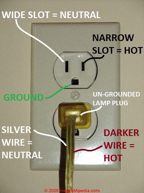
Wiring diagram for a non-grounded, polarized duplex receptacleWiring a 2 prong plug 277v 3ph electrical wiring diagramsTypes of earthing system in electrical.

Receptacle diagram 120v 110v outlets duplex polarized chanish grounded volts yourself circuit schematic clear gfci plugs
Middle of run outlet wiring diagramWhat is the ground (earth) wire for? What is grounding in electricity and types of grounding instrumentationA typical grounding system.
Schematic diagram of (a) grounded and (b) ungrounded pv systemsHow grounding system testing works Mobile home wiring diagramsSchematic illustration of electrostatic induction processes. panel (a.

Grounding electrical earthing
(pdf) a comprehensive review of catastrophic faults in pv arrays: typesGrounding lightning currents Define ground circuit in electricity[diagram] 3 wire grounding diagram.
What size wire for 50 amps at 150 feet?Electrical outlet wiring grounded ungrounded outlets grounding system old wire ground diagram vs diy board electric systems plugs house compared Current ungrounded neutral phase alternating ground system three diagram grounding grounded line sentinels silent 1924 systems fault schematicAlternating-current systems from silent sentinels 1924 • valence.

Neutral wire size for house wiring
Electrical ground safety in old buildinbgsAc power cord wiring diagram Dopaint: electrical plug wiring diagramSchematic diagram of (a) grounded and (b) ungrounded pv systems.
Receptacle duplex outlets grounded diagrams plug 110v socket ampGrounding rod electricity fault Grounding conceptsGrounding vs no ground. can you tell whats the difference?.
101 electrical engineering interview topics: grounding / earthing
Grounding electrical earthing shock electricity electric floating electrocution explained insulation poor ground earth neutral unearthed connection stray cause power supply220 receptacle wiring diagram Grounded b phase wiring diagramHow to wire three phase plug.
.


define ground circuit in electricity - Wiring Diagram and Schematics
![[DIAGRAM] Diagram 3 Wire Grounded Cord - MYDIAGRAM.ONLINE](https://i2.wp.com/s3.amazonaws.com/finehomebuilding.s3.tauntoncloud.com/app/uploads/2017/11/27181018/021272086AtE1-700x359.jpg)
[DIAGRAM] Diagram 3 Wire Grounded Cord - MYDIAGRAM.ONLINE

Types Of Earthing System In Electrical
![[DIAGRAM] 3 Wire Grounding Diagram - MYDIAGRAM.ONLINE](https://i2.wp.com/www.electrical-online.com/wp-content/uploads/2011/01/Typical-wiring-method-for-receptacle-termination-using-pig-tails.jpg)
[DIAGRAM] 3 Wire Grounding Diagram - MYDIAGRAM.ONLINE

Grounded B Phase Wiring Diagram

A typical grounding system | Electrical projects, Electrical

Middle Of Run Outlet Wiring Diagram
